Navigation Menu
Just a few things about these doodads
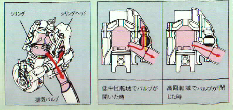
How the SAEC system works
From my paper on expansion chambers: The other type of exhaust valve I have experience with uses a small chamber (Honda ATAC, Suzuki AEC) on or near the exhaust header. This chamber greatly reduces the amplitude of the exhaust pulse, so even when the pipe is out-of-tune with the rest of the engine, it has little effect. There are SAE papers on this topic, and that's how they are described as working, so that is my understanding.
So Suzuki's AEC is also known as an exhaust antechamber. It's job is to pretty much "snuff" the wave action in the pipe, or at least, diminish it to such a degreee that it isn't able to screw things up when it's out of tune with engine RPM. How else can I put this... It's like tripping a sprinter who has just burst out of the starting blocks - the high-pressure pulse comes popping sharply out of the exhust port, and instead of a gradually-expanding headpipe, suddenly finds itself in a large room. It simply falls on its face.
I verified this theory when working with water injection in the exhaust system. From an email way back then, my thoughts on whether the SAEC re-tuned the exhaust system's resonant RPM:
I guess then, I would expect a re-tuned exhaust pipe (SAEC open) to display the same characteristics of an SAEC closed pipe, except at a different frequency, or exhibiting a different frequency response. That seems reasonable if you were to conclude that it re-tunes the exhaust pipe to operate at a different range.
The SAEC closed pipe has a strong resonance and high torque peak, with a massive valley right before it comes into resonance (on the pipe)
The SAEC open pipe does NOT have a strong resonance or high torque peak, and does NOT display the same type of behavior, and there is no massive valley before it comes into resonance.
OTOH, a water injected pipe displays roughly the same characteristic as an SAEC closed pipe, strong resonance, similar BMEP and high torque peak, and massive valley before it comes into resonance. it simply does these things at a different rev range.
Based on that, I would have to conclude that the cool, water injected pipe acts like a re-tuned exhaust pipe, the SAEC open pipe does NOT share the same characteristics as an SAEC closed pipe. In fact, it has few of the same distinctive characteristics. The absence of a high torque peak OR valley, indicate to me that there is no strong resonance present in this pipe. I do not think it is a re-tuned pipe, I think it is a pipe with very little happening inside of it. More on this topic on the water injection page.
The other approach to exhaust valve trickery is the more typical exhaust valve, which lowers the exhaust port's top edge, so that it functions as a more conservative port. YPVS barrel valves, KIPS, TZ guillotine valves, etc. They all do the same kind of thing. But.. .what if you put BOTH systems on an engine?? What THEN??
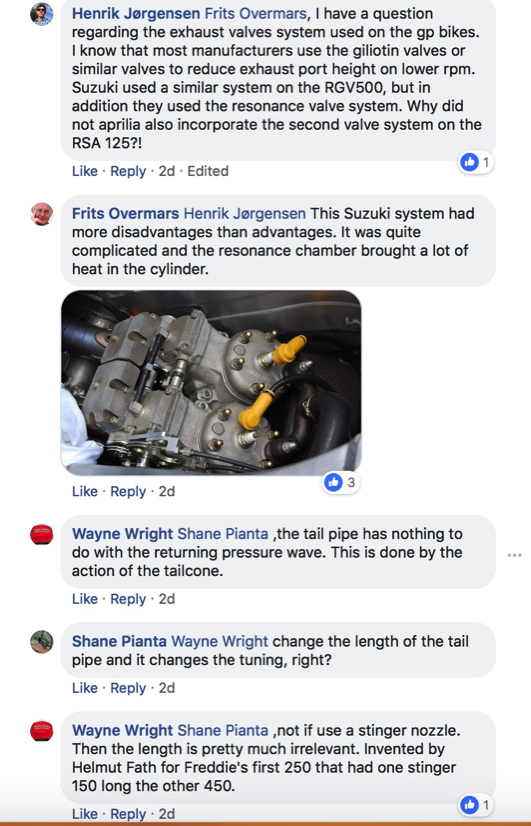
Suzuki actually did this on their GP bikes at one point. Here's a little note on that venture:
Below is a photo of a Suzuki GP engine with BOTH an AEC chamber as well as a exhaust-port-height valve.
SAEC Exhaust valve

Powervalve orientation
From Rigas : "The little line inside the PV faces to the piston side.
If placed to the wrong way around this makes the valve's home (open) position not to be full open I think.
Probably this will make it when turned to the high rpm position to be more around so reveals some area instead of full closing the area."

We keep running into this little bugaboo, and here it is again- detonation.
One contributing factor for detonation is heat. Heating the charge in the combustion chamber pushes it closer towards the point where detonation will occur. Heat in the charge comes from a lot of places, but an even-hotter cylinder head is not what you really want in a race engine that is going to be pushed to its limits.
So, then, what if you let scalding-hot exhaust gas into a chamber cast into your cylinder head? Perhaps not the best plan.
Honda used a small, separate antechamber on the headpipe, with a butterfly valve to accomplish the same task. As it turns out, this is a better way to implement such a system: the 1000+ degree hot gases are not recirculated into the cylinder head. 8-( For a racing engine, disabling the SAEC system may be a good move toward detonation resistance, although at the expense of sacrificing the surprisingly effective AEC system.
OK, so Honda had a better plan on that one.
SAEC switching RPM
Since the AEC basically makes the pipe a non-factor, we ONLY want to use the AEC until the exact moment that the pipe starts to work. If the stock system rotates the SAEC at 7800 RPM, that's because Suzuki determind that 7800 was the moment that performance of the pipe became sufficient to turn off the AEC.
But remember, a stock RG peaks around 9000 to 9500 RPM.
Also, the ideal switch RPM is not always exactly the same because of how hot the pipe may or may not be as you come up onto the revs, but we have to do the best we can and comromise. For example, if the valve is fixed in high RPM position: if you hold the gas wide open as it pulls up the RPMs, and let the bike choke and blubber slowly until it comes onto the pipe- you also have a very cool pipe because of that. The powerband will be moved down slightly in the revs. It will act more like a long pipe. If you are coming out of a long, fast corner that was taken at part throttle but mid-RPMs, the pipe may already be fairly hot.
At any rate - if you tune your engine, and install pipes that rev 1000 RPM higher, or you install a torque pipe that makes power SOONER , or basically you change anything that alters the RPM band of the engine ... The AEC timing could probably stand to be adjusted so that it is still optimized for your powerband.
All the little things add up. Getting the ignition timing just right. Getting the jetting just right (yeesh, tell me). Getting the pipe just right. ... getting the exhaust valve timing just right.
During dyno testing, I had determined that the stock AEC operating RPM was not correct for my re-tuned engine. This is a simple thing to see on a dyno. You can also determine this by riding the bike, and testing.
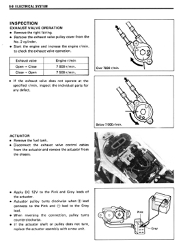
How to disable the SAEC valve
By the way, don't do this testing unless your valves are installed correctly and operating correctly! Trying to test things on a system with binding cables, valves installed backwards, etc, will be a waste of time.
If the bike is off, turn the key on and the servo will rotate to the low RPM position (AEC valve chamber is open to the exhaust). Try it- with the tank off, rotate the pulley on the servo by hand to the high RPM position. Turn the key on, and the servo will rotate back to the low RPM position again. Turn the key off, and you can just unplug the power to the servomotor at this point. So now you're stuck in low RPM position.
That is the simplest way to disconnect the system, but it's more of a hassle when testing. Go for a ride and check out your neutered motorcycle.
Now come back and manually rotate the pulley to the stop, in the other direction. The valves will be in the high RPM mode (antechamber NOT connected to headpipe). Go for a ride. There will be a big DIP in the power, before the bike comes on the pipe. That, amazingly, is what yor SAEC is able to fix. Amazing, huh?
Getting the valve to switch at just the right RPM is the key to a smooth powerband (and maximized) power curve.
In my case, I interrupted a power lead to the SAEC servo and put a switch where I could reach it. I was able to ride around and test with the valve open, or closed, easily.
To get the valve into the Hi RPM position on an assembled bike, just rev the engine over 8500 or so and flip the power cutout switch while the valves are open. Then, they will stay there. In this way I was able to change back and forth, and figure out where the best switch point should be.
This can also be determined on a dyno.
Testing for correct powervalve RPM setting
You just make three dyno pulls.
1) pull with exhaust valve on auto
2) pull with exhaust valve open
3) pull with exhaust valve closed
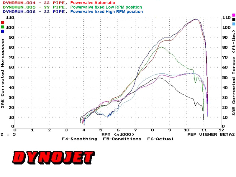
Then, look at the graph and see where the open vs closed curves cross!
With SAEC fixed in hi RPM position, you can see the terrible dip before the bike comes on the pipe - part of this is because we were testing at WOT, and so the without the SAEC, the pipe resonance produced a rich "hole".
You can also see how incredibly effective the SAEC system is at defeating the action of the pipe, when fixed in low RPM position. There is simply no top end power at all.
This should also give you some idea how badly a nonfunctional or improperly-functioning SAEC system can screw up your power output. Installing the valves backwards, binding cables or a half-dead servo or control unit can really mess up the whole party. This simple little system HAS to work, if you run it on automatic. Even better, it has to switch at the correct RPM for YOUR particular combination. Otherwise, you are just leaving HP on the shop floor. In my case, the stock RPM switch point was too late. With the SAEC closed, the pipe literally does not work until ~ 8000 RPM. By opening the valve early, I picked up 10 hp at 8000 RPM. Is it worth chasing that? It's up to you!
The rich hole can be addressed by other means, as well, such as boost bottles or water injection.
Adjustable valve operation setpoint
When I first discovered that the AEC switching setpoint was not optimized for my engine, I contacted James walker at BDK Race Engineering in the UK. This clever fellow not only modified the OE CDI to have diffrent advance curves, he was game to modify the powervalve control module to similar effect.
So, after a bit of begging and waiting, a BDK adjustable SAEC control unit arrived on my doorstep. With a handy little twist knob, I was able to tune the valve setpoint as desired. It was bloody fantastic.
Nowadays, you can still get this unit from BDK, apparently. I would for sure have one on my bike, if I didn't have that control in my ignition.
Here's the info from their website
Performance Fabrications used to sell one, but I can't find it on their website.
You can also get an Ignitech or Zeeltronic ignition which have the ability to control the powervalve.
What to do if the AEC servomotor dies?
Well, you can go shopping for another 30 year old servo, or you can fix it, or you can install a newer servo. I'm using a Zeeltronic, which can drive a Yamaha exup servo. The exup servo basically has a 5-wire connection, 3 wires for a typical position sensor (like a TPS) and two wires for power.
EXUP servo connection info here
The R6 exup servo I am using on my bike
Troubleshooting for Electronic Geniuses
So, what if you want to fix your standard powervalve servo unit? Here are some conversations about what's in there. and what can go wrong:
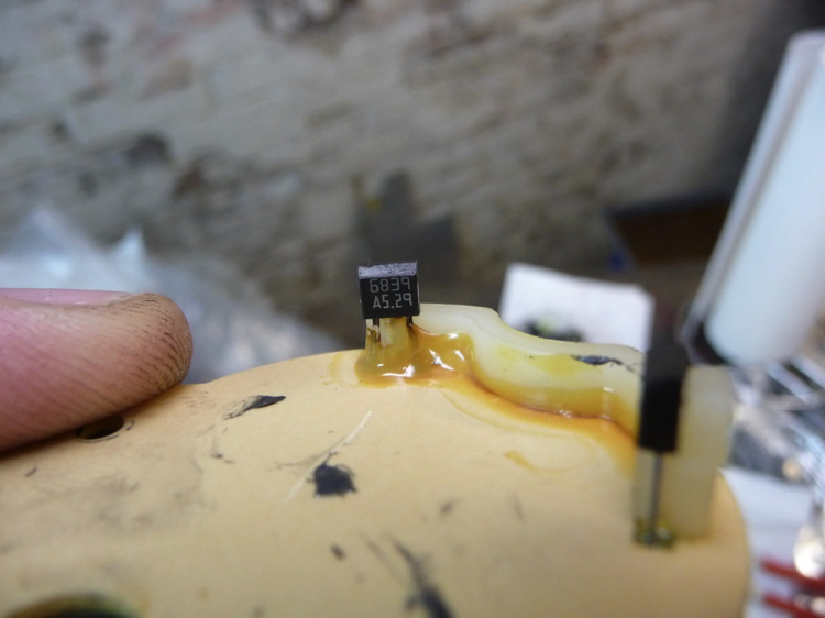
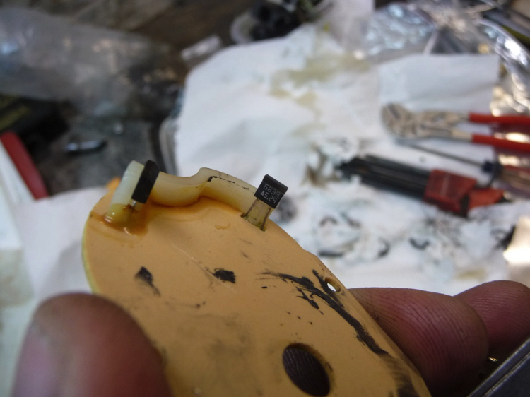
Short story: There are transistors inside the control unit. They are connected to a small heat sink strip and buried in potting compound. A very slow, draggy motion on the valves can cause the transistors to overheat. Then - you have to replace transistors.
There are hall effect sensors that act as position limit sensors on the motor. They can fail as well. Keep reading to see where they are and what to replace.
Finally, there is a time-out failsafe on the motor. It will only "try" to turn for so long before it gives up and stops. This is to prevent (hopefully) motor or component burnout. On the Delta engine, I used the stock PV motor to turn my TZ powervalves. The travel distance was incorrect (less travel than an RG valve) but it simply turned to the limit of travel, tugged on it for an extra second or so, then stopped via the timeout.
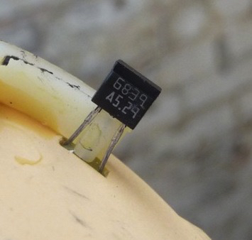
Peter Stolcs said, on transistors:
"I had a similar problem except my AEC controller would not rotate the valves to the "open" (Lo RPM) position. I inspected the cables and found that the previous owner had installed 2 cables incorrectly which resulted in one cable binding / not leading onto the cable drum correctly.
The result was blown power transistors in the AEC controller.
The transistors are a bastard to replace because they have OEM markings, I had to find out the characteristics of the good set (PNP's for Hi RPM position) and then get a matching set of NPN's to replace the damaged set (I replaced all 4 with higher value units). 4 power transistors (2 NPN and 2 PNP) are used to swing / reverse the polarity of the supply voltage on the AEC Servo motor, if there is any hint of overload on the motor (stuck valve / binding cable) the respective transistor pair overload and self-destruct.
You could dissolve the potting compound in thinners and replace the damaged transistors but this is not an easy task. It's a shitty job that will take about a week for the thinners to dissolve the potting compound, even then, there are enough plates and insulators between the pc board and the metal case that make it's extraction a pain in the ass.
There is an aluminium strip which acts as a heat sink for the power transistors, it's pressed against the inside of the metal case and is a bastard to get loose. Potting compound gets between a plastic insulator, the pc board and the metal case, thinners can't get to the compound and this makes extraction tricky.
Thinners will (may) attack the rubber stoppers on 2 of the electrolytic capacitors used in the circuit. This is no big deal because they are easy / cheap to replace and even if they are not damaged, it would still be best to replace them. (my opinion)"
Sticky valve operation and motor speed
More conversation on PV motor and controller
SAEC tech talk ridiculous RG fan Stolcs
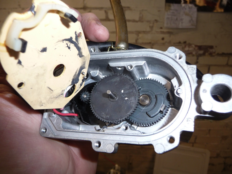
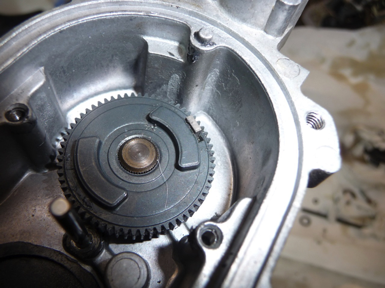
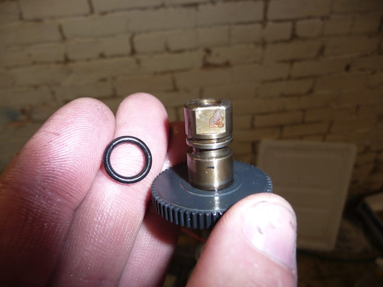
Below are a few pics of the hall effect travel sensors inside the servomotor. These are the easy things to fix, as far as that goes.
Click image to enlarge cutaway of SAEC system


As delivered, the stock SAEC controller switches to high RPM mode at 7800 RPM, and back to low RPM mode at 7500 RPM.
One anecdote here: when drag racing my bike with the stock transmission and stock-ish powerband, the gap from 1st to 2nd was so large that the bike would fall below the closing RPM upon shifting into 2nd.
There would be a moment of hesitation as the valve cycled open, then hurriedly cycled shut again in 2nd. I found that when dragracing, it was preferable to lock the valve in the high RPM position and keep the revs above 7500 for the launch, etc.
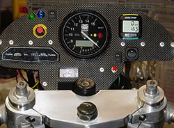

SAEC adjust is the red/yellow dial on the left side, circa 2003